| Characteristic |
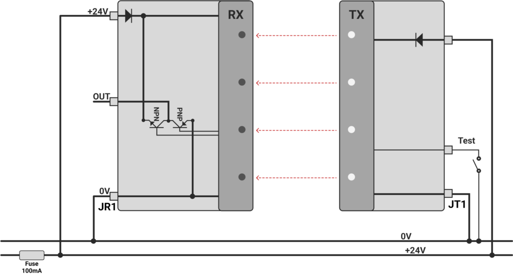
SO Exit |
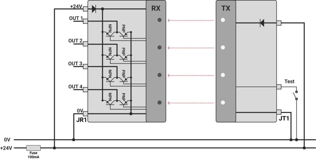
MO Exit |
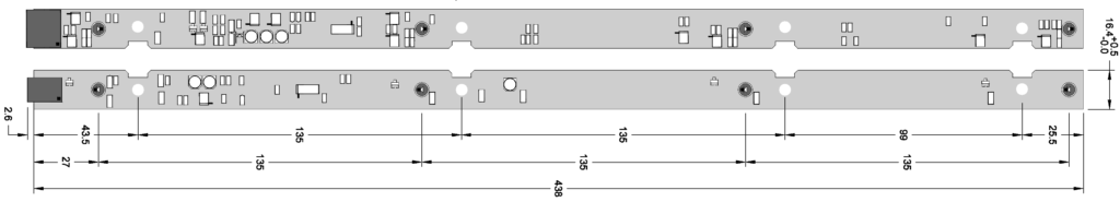
| Beam centre distance |
135mm |
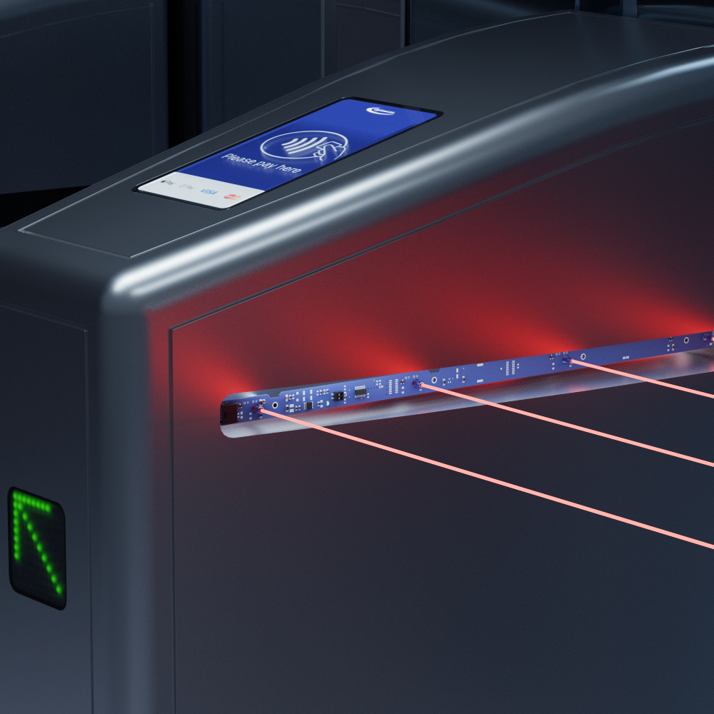
| Range |
0 - 6m |
| Wave Lenght |
880nm |
| Light immunity |
>100Klux |
| Temperature |
from -20°C a +60°C; Maximum relative humidity of 95% |
| Supply voltage |
24Vcc +/-20% |
| Power consumption TX + RX |
35mA without load |
| Status LED | GREEN LED on TX, flashing when test is activated |
| GREEN/RED LED on RX |
| Test input |
0 - N.O. (0V active test) |
| Response time |
10ms |
| Reset time |
20 - 40ms
|
| Test activation time |
12 - 20ms |
| Output |
0-24V Push/Pull;
I max: 50mA |
4x 0-24V Push/Pull;
I max: 50mA |
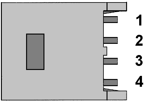
| Connections |
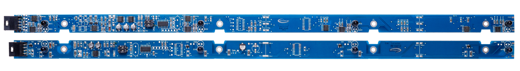
TX male connector
4 pin AMP MODU II | TX male connector
4 pin AMP MODU II |
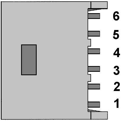
| RX male connector
4 pin AMP MODU II | RX male connector
6 pin AMP MODU II |